All About Wireless: System Planning, Coordination and Monitoring

Welcome to the thirteenth and final installment of All About Wireless. In this issue, we will discuss best practices regarding site evaluation and frequency coordination planning. We will look closely at Shure Wireless Workbench (WWB) to highlight ways in which the software application can assist with inventory management, frequency coordination, and the real-time monitoring of wireless microphone and IEM systems.
Effective Radiated Power
When planning an RF system for an event or facility, the first aspect to consider is the physical location of the installation. The postcode or geo-coordinates of the installation location provide a critical starting point for assessing the RF environment. This information can be used to determine the distance from TV and public safety transmitters.
To predict the on-site broadcast signal strength, the Effective Radiated Power (ERP) of each station needs to be considered in conjunction with the physical properties of the propagation path.
A typical ERP value for a low-power station is 15kW. ERP for a major station may be as high as 1000kW, an increase of 18dB. Propagation considerations are largely influenced by topographical features such as transmitting tower elevation relative to the site and obstructions from mountains or buildings.
In some locations, it is also prudent to consider distant cross-border transmissions as these may also contribute to an increased RF noise floor. The impact of these transmissions on a wireless microphone or IEM system will depend on if the system is to be installed outdoors or indoors. The additional shielding that a building provides against external interference may enable the successful operation of an RF system indoors that would otherwise fail if installed outside.
The Shure WWB application references a comprehensive database of active TV transmitters for many regions across the globe. Accessible via the Frequency Coordination tab, the TV Channels database allows RF Engineers to search for a location and automatically exclude frequency ranges with active TV transmissions from coordination.


Once the RF Engineer has identified the spectrum within which the wireless microphone or IEM system can operate, a deeper understanding of the physical environment is required. In order to effectively design an antenna, transmission line and signal distribution system, the RF Engineer requires detailed site information. This includes a clear specification of the intended coverage area(s) and details of any interior structures that may obstruct the propagation of RF signals.
Site floor plans are essential for determining potential antenna locations and the associated cabling requirements. If the RF Engineer will not have the opportunity to visit the site prior to the system installation, photos of the venue can be invaluable. This is particularly useful for identifying potential sources of EMI on site.
System Inventory
The next key consideration is the system inventory. This is not limited to the inventory of hardware to be installed. It is also important to obtain a detailed inventory of any existing wireless systems installed on-site and any additional equipment that is expected to be brought onto the site (ENG systems, for example).
At the very least, it is essential to know the brand, model and frequency band of all wireless hardware on-site. For existing installed systems, it is also important to know the operating frequency, RF power level, and area(s) the transmitters are used in. Once these details have been collated, the full system inventory can be built within WWB.
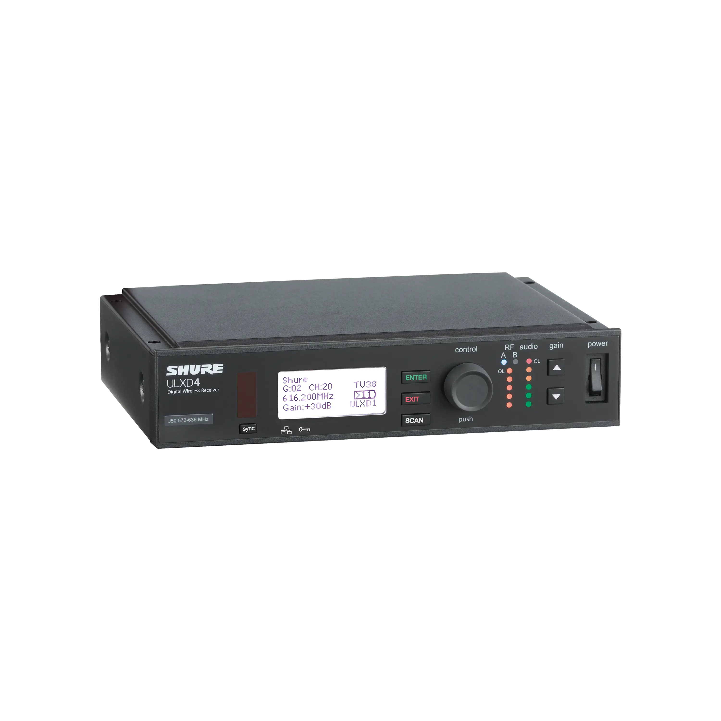
The Inventory tab in WWB can be used to add, label and organize all wireless devices in the system. Parameters for networkable Shure devices can be pre-configured both individually and as batch edits to multiple devices of the same type.
Device pre-sets enable RF Engineers to save sets of key hardware parameters to file so that they can be quickly applied to one or more selected devices in the Inventory. Once the equipment is installed on-site, these pre-configured settings can be automatically uploaded to network connected Shure hardware.


WWB does not limit the RF Engineer to working exclusively with Shure products. Equipment profiles exist for wireless microphone, IEM and intercom systems from several other manufacturers. The software also allows for the creation of custom profiles, so RF Engineers can add their own profiles for any equipment in their inventory for which a pre-defined profile does not exist. The equipment profiles are designed to ensure that the frequency coordination allows each device type adequate bandwidth for stable operation.
In addition to these robust inventory management features, WWB provides a sophisticated toolset for frequency coordination and live system monitoring.


WWB features visualization tools facilitate monitoring of the RF spectrum via plots and scans. Analysis tools examine scan data and existing frequency assignments to calculate compatible frequency lists for deployment to system hardware. The Frequency Coordination plot displays selected scan data, exclusion ranges, inclusion ranges, and defined frequency markers. Spectrum scans may be conducted by network connected Shure devices, or the scan files generated by third-party products (Winradio or TTi scanners, for example) may be imported for consideration when performing a frequency coordination.


Spectrum Scans
Spectrum scans are therefore critical to ensuring that the RF landscape on-site is accurately captured and considered when performing a frequency coordination. When assessing the site prior to installing the system, it’s important to make multiple scans across all areas of the venue.
If the system is to be installed indoors, it is still important to conduct scans outside of the venue so that the shielding properties of the building can be assessed. Scans are useful for confirming the power levels of TV broadcast, out-of-band commercial transmissions (public safety, paging, mobile network, two-way radio etc.) and local EMI sources on site. Scans can also help to identify non-documented sources of RFI on site.
There are a plethora of RF scanning tools available in various form factors from a multitude of manufacturers. While some scanners (typically portable handheld units) are aggressively priced, it is important to remember that these affordable units are typically less accurate and feature rich than more expensive scanners.
Cheaper scanners may measure the RF noise floor incorrectly, miss transient spikes of EMI, or introduce spurs of EMI themselves that wouldn’t exist otherwise. Considering the data obtained from these units is critical to the frequency coordination process, it’s worth ensuring the scanner in use is capable of accurately representing the RF environment.
Shure recommends using the AXT600 wideband Spectrum Manager, but if this is not available, any network connected Shure receiver can be used to perform scan of its particular operating band. Ideally, site scans should be conducted via the same antenna, cabling and signal distribution infrastructure the RF system will use. If this is not possible, a Shure UA860SWB passive omnidirectional antenna positioned at the approximate system antenna location is the next best option.
Exclusions identified via the spectrum scanning process and TV Channel database search will automatically populate the WWB Additional Exclusions list. It is also possible to manually add single frequencies and frequency ranges to this list if the RF Engineer feels there may be additional sources on interference that were not identified in the scans. This process is vital to ensuring the system is coordinated to use the cleanest and most available ranges of spectrum.


WWB provides several tools to facilitate enhanced user control over the frequency coordination process. The Scan Plot window features overlayed red and orange horizontal lines that represent the user-defined Exclusion Threshold and Scan Peak Threshold respectively.
The red Exclusion Threshold represents the maximum allowable noise floor over which operating frequencies may be coordinated. Active transmitters identified during a scan that exceed the Scan Peak Threshold are automatically assigned a profile to ensure a frequency buffer is maintained around the peak frequency. The assigned profile may be changed by the RF Engineer to vary the bandwidth of the safety buffer if the source of the Scan Peak is a known quantity.
This process ensures that available bandwidth is not excluded from coordination unnecessarily while minimizing the risk of interference to coordinated channels.
Wireless Workbench Compatibility Level Profiles
WWB provides three default compatibility level profiles that determine the allowable coordination density – Standard, Robust and More Frequencies.
The Standard setting uses a default channel spacing, ideal for use when a balance between robust operation and maximum frequency count is desired.
The Robust setting employs a more conservative spacing designed to provide priority channels with greater isolation from potential interference.
The More Frequencies setting applies an aggressive spacing profile in order to coordinate a greater number of frequencies within the specified bandwidth.
When performing a frequency coordination, dragging and dropping device types or inclusion groups in the coordination list allows the RF Engineer to customize the order in which frequencies are coordinated. WWB will analyze the properties of the hardware imported from the Inventory, consider the excluded frequencies and coordinate a set of compatible frequencies for as many inventory items as possible.
Backup frequencies are also a common requirement, especially in live touring applications. Backups can be assigned in WWB per device type via the Request Additional Frequencies menu and coordinated along with the active inventory devices.
Once a fully compatible frequency coordination is achieved, frequencies can be manually assigned to specific devices, or they can be automatically assigned to network connected Shure devices. WWB provides an indication of the quality of a given frequency based on the level of the RF noise floor captured in the scan data. If the system includes an AXT600 Spectrum Manager, backup frequencies can be monitored continuously to ensure they remain ranked for deployment in order of channel quality.
Monitoring in Wireless Workbench
The WWB Monitoring tab exposes tools for the real-time monitoring and remote control of network connected Shure devices. The monitoring window can be configured to display a channel strip and properties settings for each connected channel. The properties of network connected Shure accessories such as chargers, ShowLink access points, ADUs and Spectrum Managers may also be configured remotely via the software.
To meet the diverse and complex monitoring requirements of many live productions, it is possible to configure multiple monitoring tab views with a different channel arrangement on each tab.
WWB extends on this live monitoring functionality in the Timeline tool. The Timeline is a real-time logging utility with a rich graphical user interface designed to capture key status information over time for all selected channels. Information recorded includes RF level, antenna status, audio level, interference, ShowLink® Remote Control status, and battery level.
Timeline can simultaneously record data from up to 120 networked channels for an indefinite period of time given sufficient system resources. In addition to this, Mini-Timelines can run in the background for each channel, continuously recording a rolling five minutes of key channel parameters.


Baselines for system performance can be established by using the Timeline functionality to map RF performance over time. Playback and analysis of captured data yields valuable insights into audio performance and the associated RF conditions.
When employed as a documentation and archiving tool, Timeline can be used to quickly pinpoint anomalies or display transient events, even over a period of days or weeks. Capturing and viewing the recorded Timeline data therefore enables RF Engineers to more effectively commission new systems, troubleshoot problematic systems, and validate the on-going operational integrity of installed systems.
This brings us to the end of the ‘All About Wireless’ series. Additional information regarding wireless microphone and IEM system design, operation and troubleshooting are available via the Shure Audio Institue (SAI) platform. SAI is an educational and networking platform that provides systems integrators and consultants, MI retailers, the Pro Audio industry and musicians access to a diverse selection of online courses, instructor-led workshops and seminars.